The Commodore 64 Polyphonic Multitimbral Synth
20.10.2024
23.10.2024
24.10.2024
29.10.2024
03.01.2026
10.01.2026
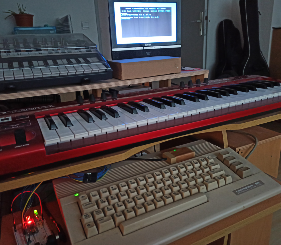
Updated MIDI Compatibility
There is a new version of the Arduino sketch (3.1) that is
compatible with MIDI controllers that use Running Status
(i.e., devices that omit repeated status bytes when
consecutive MIDI messages share the same status) or that
send periodic Active Sensing signals. With the old version
(3.0 still available
here), some MIDI
controllers may exhibit missing notes, stuck notes, or other
unexpected behavior.
Download the new version
Polytimb_64_3_1.ino
* * *
Introduction
The goal of this project is to build a polyphonic multitimbral analog synthesizer with the SID chip, using a Commodore 64 and trying to fulfill three requirements:
1. It must be playable
as an instrument with any MIDI keyboard, connected to the user port through an Arduino interface.
2. It must be
as standard as possible: minimal soldering, neither drilling nor opening the computer case.
3. And as inexpensive as possible: only an old (working) Commodore 64, an Arduino board and a
few of electronic components are needed.
The most expensive device will be the SD2IEC drive
you'll need to load the program, unless you are willing to type it manually.
If you are going to buy an
SD2IEC drive, please make sure you get one that connects to some C64 port
other than the user port,
as the user port will be used for the interface described
on this site.
New in v 3.0
● Vibrato
●
Oscillators fine tuning
● Notes routed through the
filter can restart or not the filter envelope.
● The LFOs
for the pulse width and filter cutoff can now also oscillate
with a square wave.
●
Now it's possible to split the keyboard at any point (not
necessarily at a C) just by pressing the desired key,
instead of repeatdly pressing a button to shift the split
point.
● There are fewer garbage characters on screen.
● You can optionally add three push buttons to the board to
select the polyphony modes and keyboard split (otherwise,
this can be directly done from your MIDI controller as in
previous versions).
Disclaimer
My electronics knowledge is very elementary.
I can't guarantee you won't fry a chip by building this project. I can only say I've spent many hours with wires and pins, both in Arduino and the C64 user port, and nothing
went wrong. I read very carefully lots of documentation available in the net before trying anything, so those readings are my only advice if you
want to avoid accidents. If you know more, I'd appreciate any safety tips you could provide to this section.
I had never soldered before this project and it took me some practice to
make firm solder joints on the user port connector (German).
This was the messy first attempt, but it worked well though.
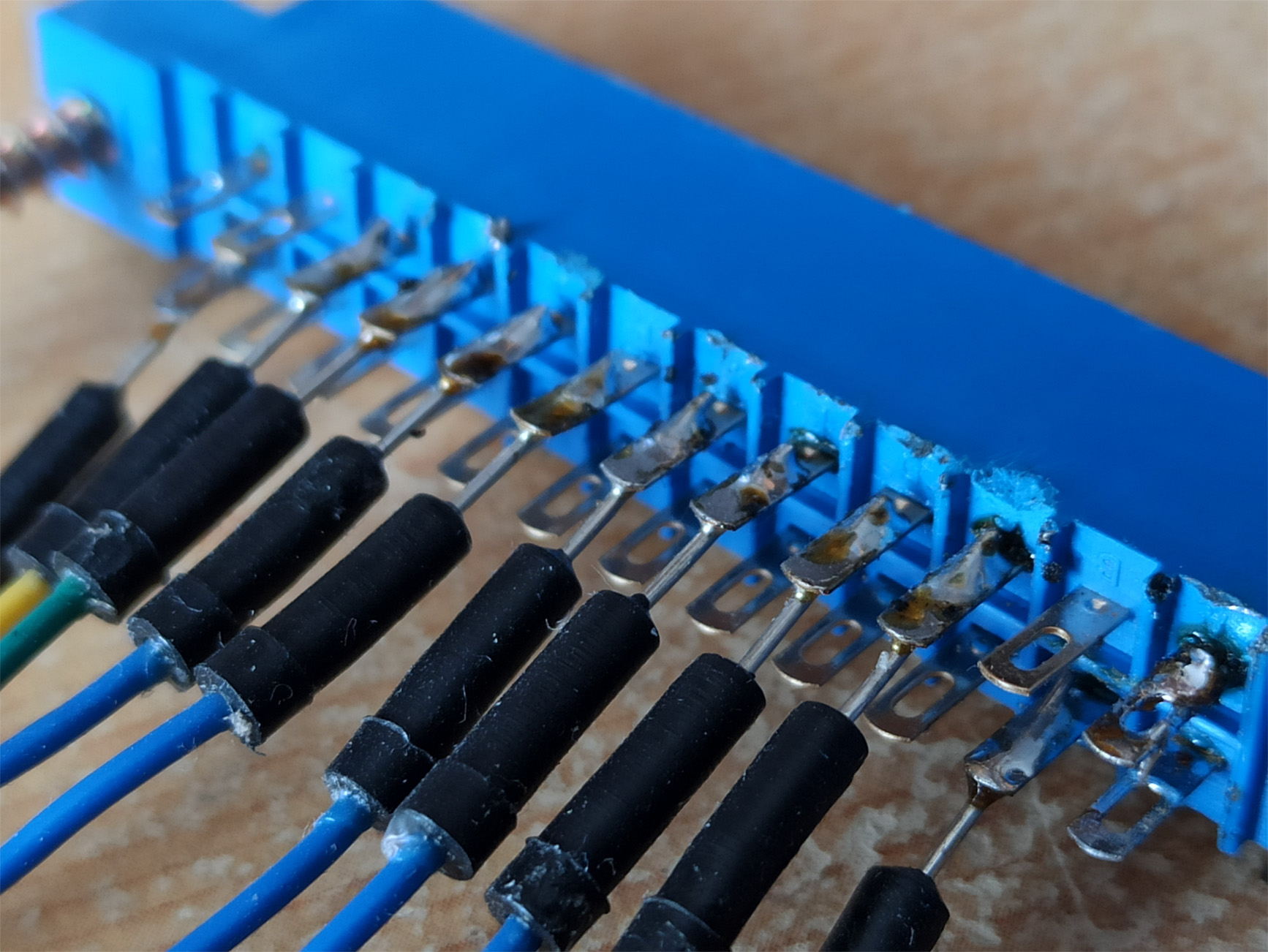
Later on I used longer wires and managed not to burn the
edges of the connector.
Please don't use any batteries to power the Arduino. In other projects I've used a 9V battery connected to the Vin pin, but I’m not sure if this could damage the C 64.
Anyway, in this project the Arduino works fine with the 5V provided by the C64 user port. Alternatively, I unplugged the 5V and GND wires that connect Arduino and the C 64 and powered Arduino with a USB cable from the PC instead; this worked well too, although I tried it only for
a few minutes.
Here or here you can see the Commodore 64 user port pins.
During the development I've used different setups with two Commodore 64 C
(this model has the 8580 SID), an Arduino UNO and
an Arduino Nano, and they all worked fine. I'm using Arduino Nano now due to
a lack of space on my desk. I’ve never tried it with a Commodore 64 equipped with the 6581 SID, but it should work as well (feedback on this will be appreciated).
On the internet you can find MIDI in/out schematics, and how MIDI data
is sent/received in Arduino. For this project only MIDI IN is required, which is a bit more complicated than
MIDI OUT, but still pretty easy to build.
Parts
General
● Breadboard: 2 split power buses, 10 columns, and 63 rows
(see the image below).
● Jumper wires in different lengths.
● Soldering iron
● User port connector (English)
For the MIDI circuit
● MIDI connector
● 220 Ohm 1/4watt resistor
● 1N4148 diode
● 10k Ohm 1/4 watt resistor
● 470 Ohm 1/4 watt resistor
● 6N138 optocoupler
Other parts
● 3 x LEDs. I've used green, but I assume other colors should work as well.
-
Alternative A (new) 3 x 220 Ohm resistors, one for each of the 3 LEDs.
-
Alternative B (old) 1 single resistor for all 3 LEDs: 1k Ohm resistor
or a 470 Ohm resistor, it all depends on
how much light you want the LEDs to emit.
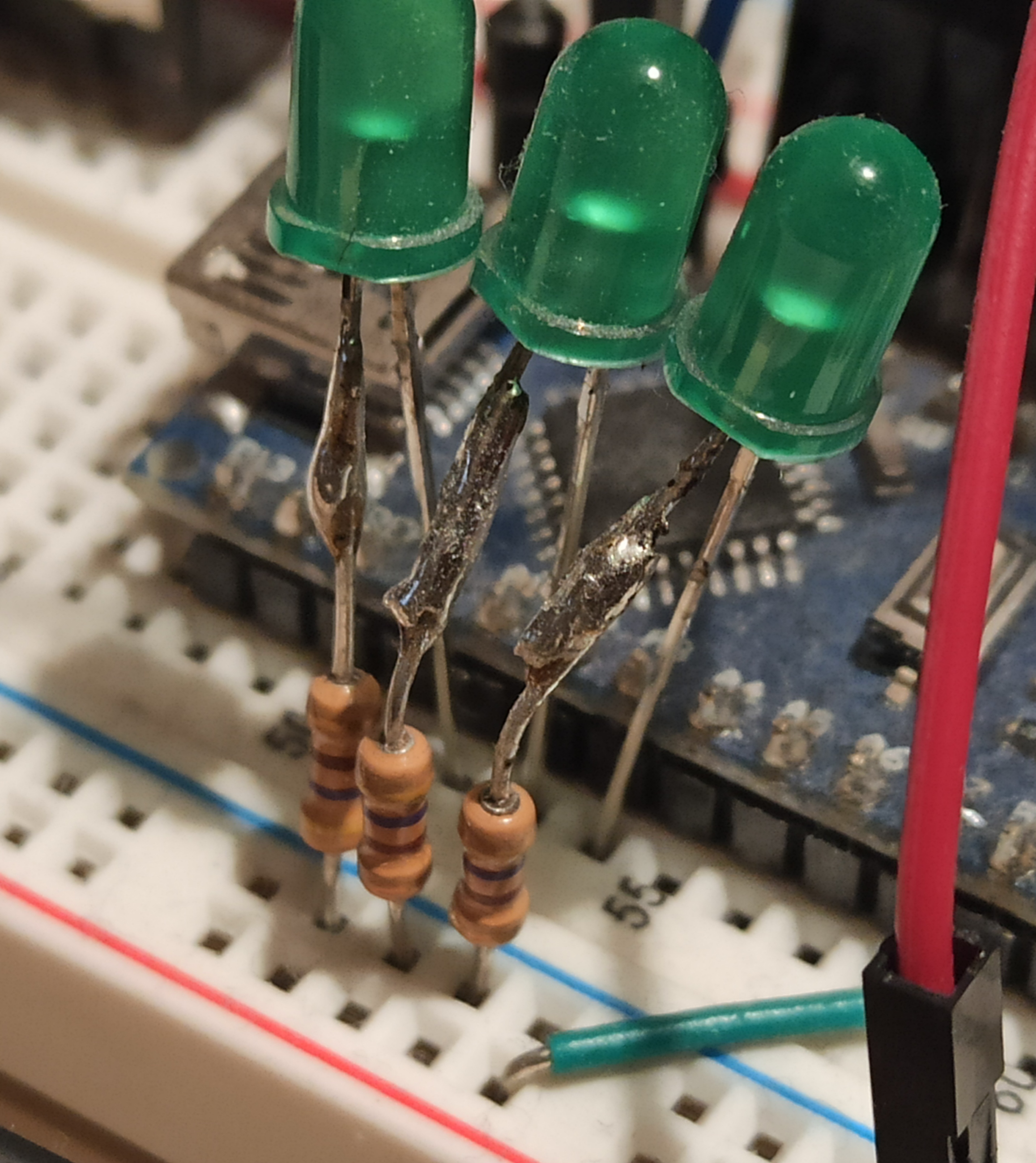
The alternative A produces a more balanced light in
the 3 LEDs, regardless of how many of them are lit, but might be a bit more
complicated to build: I´ve
soldered each 220 Ohm resistor to an LED but you can also
wire the Arduino pins to free holes on the breadboard and
then connect the LEDs from another hole in the same column
as the wire to the GND power bus.
● 3 x
pushbuttons (optional*)
● 3 x 10 K resistors (optional*)
* These
optional parts are used to select
keyboard modes and set the split point by pressing pushbuttons, but
this can be done much more easily by sending control changes from your MIDI controller.
They are only necessary if your MIDI instrument lacks proper buttons to
send MIDI messages.
The
Arduino sketch works with both
circuits: with and without pushbuttons.
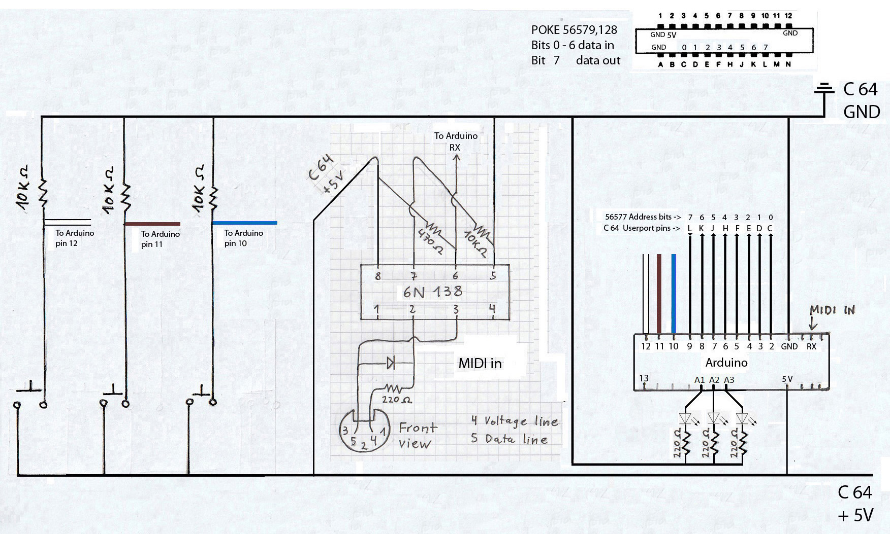
Below are the schematics and
some pics.
Please note that in the schematics the 8 bits
in Arduino are assigned from right to left (0 to 7) to the digital pins 2 to 9, while in the user port (viewed from outside) these 0 to 7 bits are assigned from left to right to the pins C to L.
In the next picture you can see that I've used a switch to
connect and disconnect the line that carries the MIDI messages to the RX
pin. When uploading the sketch this line must be disconnected, but
it's not necessary to build this switch, you can simply unplug the MIDI IN wire
instead and plug it back in once the upload is complete.
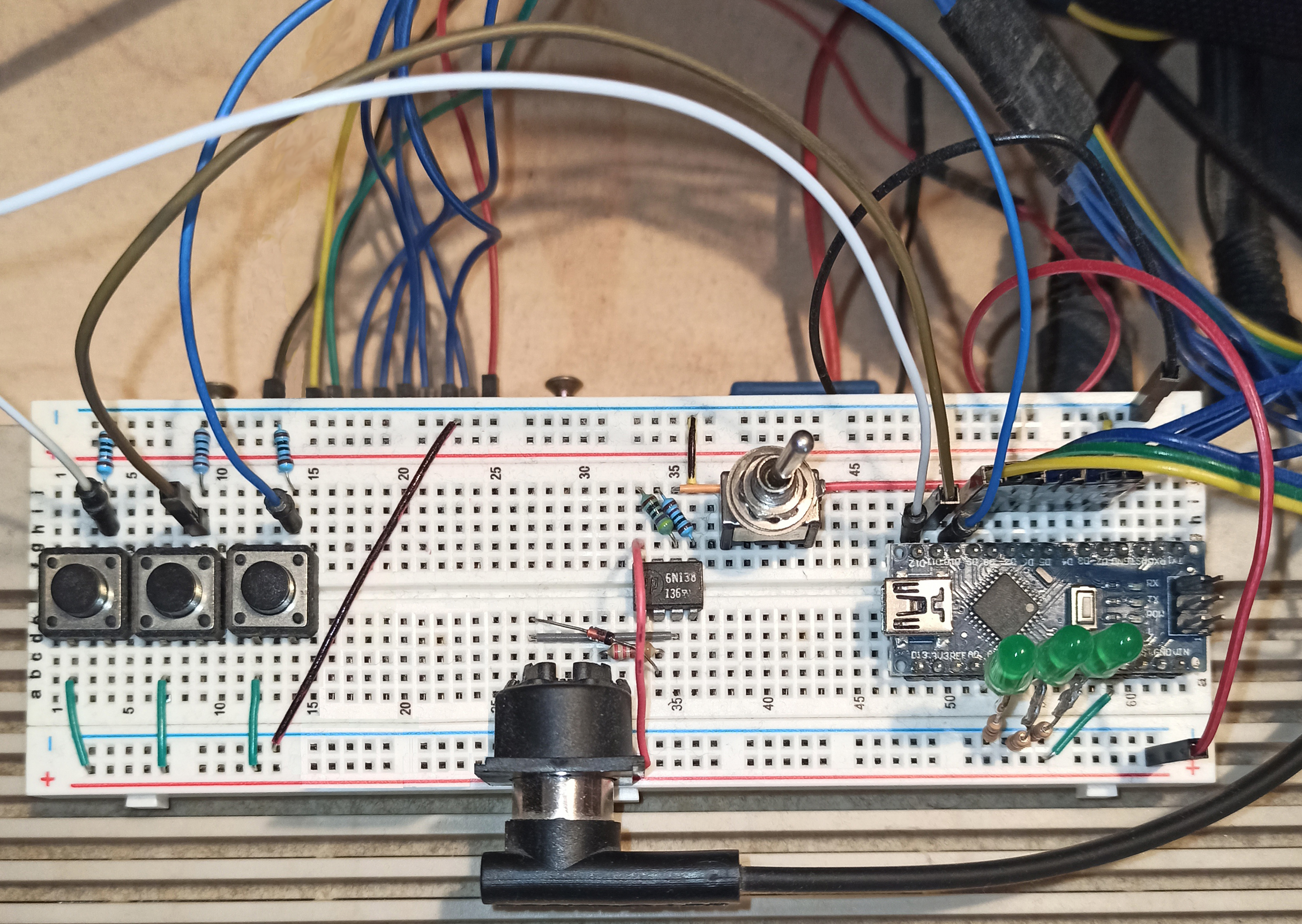
And this
was the first, not so neat but simpler attempt, with a single 1k resistor for the 3 LEDs.
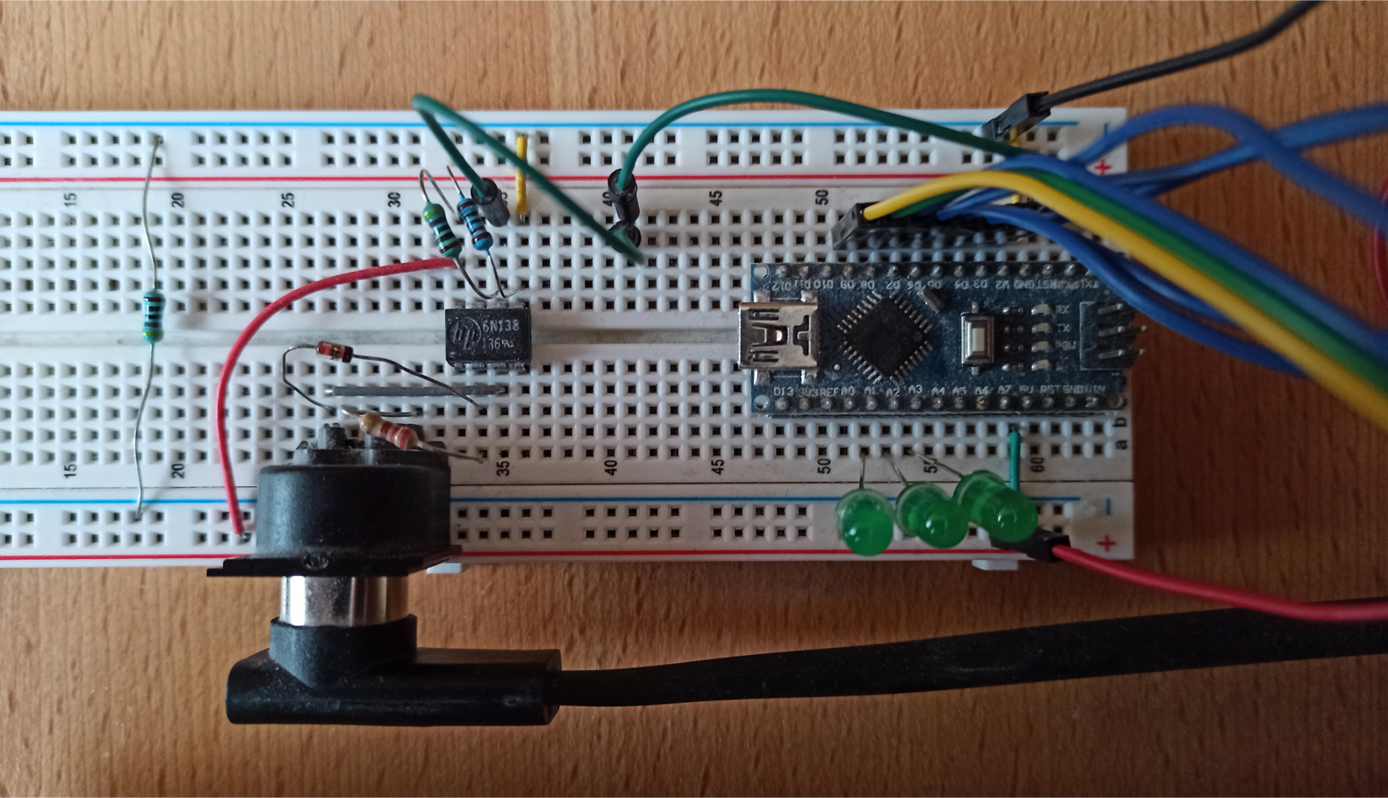
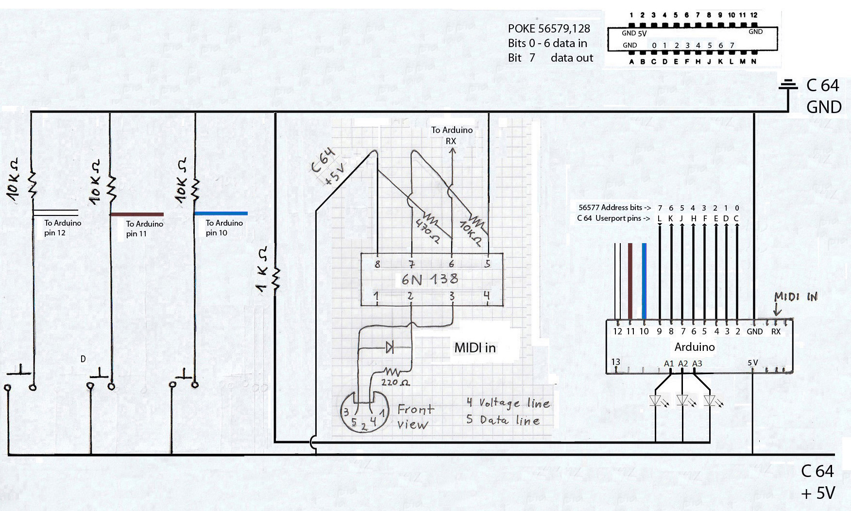
Now follow these
steps:
• Build the circuit.
(If you want to see how it looks as a PCB, you can
check out
here
how Matteo made it, with a couple of hardware additions).
• Upload
the sketch to Arduino. When uploading it, please
don't forget to unplug the MIDI IN wire that goes to the RX pin
on the Arduino.
In the picture, this is the wire that goes through the
switch, but, as I mentioned, the switch is not necessary. Once
the upload is complete, plug the RX wire back in.
At this point you can perform a quick check: connect your MIDI
controller to the MIDI connector on the breadboard and press and release
some keys. Each time you press a key, the built-in LED on the Arduino should briefly
blink, and the same should happen when you release the key. If this is not
the case, something went wrong with the upload or some parts aren't
properly connected in the circuit (see the
troubleshooting section).
• Connect the Arduino to the C64 user port.
Both Arduino and the C64 must be off.
In fact, Arduino will always be off when the C64 is off.
Once the hardware is connected, you can also upload the sketch while the C64 is on, but in some cases this can cause lock-ups.
• Turn on the C64 and load the program with
LOAD"POLYTIMB 64 3.0",8. You can
download it here, transfer it to a SD card, and read the file using an
SD2IEC drive.
Alternatively you can load the program in a PC emulator, read it on screen and type
it into the C64; this is tedious and can cause lots of bugs
due to typing errors, but it is an option.
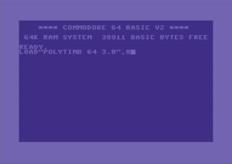
The BASIC code is a
spaghetti mess, and the user interface is not very
user-friendly, but it works.
You'll see some garbage characters I've been using as a kind of visual debug
to pin down what's going on in the machine language routines. Someday I'll
clean it up. The machine language code,
however, is pretty optimized and
clean.
Once the program is running, please be careful
when entering data. Values outside
the range 0-255 aren't checked for
validation when you enter them and will cause an ILLEGAL QUANTITY ERROR. If
that happens, you'll
have to restart the program.
In any case, all
of the SID's paramaters can be edited and you can save and load
patches.The
keyboard can be
split
in two parts, each of which can control one or two of
the 3 SID voices. If not split, the
entire keyboard controls
all 3 voices
(full polyphony). There are 6 different modes (see below).
To tune the SID,
I'm
using the PAL frequency, as shown in
this table, where C-0 is 278. In line 1 of the BASIC
program, this is divided by 1.0595 so that
FI=262.39 (and multiplied again by it in the
loop of lines 7-8 to get the frequency of the first 12
semitones). If you are using NTSC, you might need to set
FI=252.95 in line 1, so that the
frequency of C-0 is 262.
Polyphony
modes and keyboard split
(MIDI CCs or push
buttons)
There
are three functions you can control using control changes from your MIDI
controller or with push buttons from the Arduino circuit.
1.
Cycles through the 6 modes: 1 > 2 > 3 > 4 > 5 > 6 > 1. This is
CC #97 or the push button connected via the white wire.
2.
Sets the point where the keyboard is split. After pressing this button,
just press the desired split point note on your MIDI keyboard. This is CC #96 or the brown
wire. Please make sure you press only one key
on your instrument at a time; if you play more, the program might
start to become unstable, keeping notes on when they should be off.
3.
Swaps the left and right parts of the split keyboard. This is controlled
by CC #66 or the blue wire.
If
you want to use different control changes, you can search for "97", "96" and
"66"
in the Arduino sketch and change them to other values. Alternatively, you can
assing the CCs to other buttons, sliders or knobs on your MIDI
controller in real time (although sliders and knobs will be a bit tricky
to tweak, requiring very precise finger motions). To reassign CCs, touch any control other than the three
you are currently using. You'll see that two LEDs start to blink
rapidly. While they are blinking, touch the three
controllers you want to assing to CCs 97, 96 and 66, one after another. When all
three are assigned, the LEDs will stop blinking.
Check out a video here.
|
|
|
3 independent voices/oscillators: Fully polyphonic,
allowing you to play up to 3 notes at the same time across the
entire keyboard.
|
|
|
|
Voice 1 is on one half of the keyboard, while voices 2 and 3 coupled on the other half: you can play one note on each half of the keyboard.
On one half, voices 2 and 3 are triggered simultaneously when you press a key; you can detune the voices, synchronize, or ring modulate voice 3
with voice 2.
|
|
|
|
Voice 1 plays "pseudochords" on one half of the keyboard,
while voices 2 and 3 are played independently on the other half. The pseudochords allow you to play up to four notes
simultaneously on
one part of the keyboard; those notes are actually played like an arpeggio, and when played fast enough, they sound almost like a chord (a well known effect you
may have heard in many games).
|
|
|
|
Voice 1 plays "pseudochords" on one half of the keyboard,
while voices 2 and 3 are coupled on the other half.
|
|
|
|
Voice 1 is on one half of the keyboard, while voices 2 and 3
are on the other half, but they are not coupled. This is similar to mode 1, but you can use different
sounds in two separate parts of the keyboard (multitimbral).
Alternatively, you can use the same
timbre in both halves, but ensuring that the notes on one half never override the notes being played in the other half.
|
|
|
|
3 voices coupled. This is a monophonic synth with 3 oscillators. You can detune any of them, synchronize or ring modulate to each other.
|
Once you run the program, you will be prompted (Y/N) to read the data for the machine language code and
the tables used
by it. You
should select "Yes" the first time. If for some reason you have to
restart the program without
turning the computer off, you can bypass
this by selecting "No"
to save some time. You might need to restart the program
if you enter a wrong value while
editing a patch or
accidently
press
Run/Stop. The program is still in development and it's not very user-friendly in
this
regard.
Things that can't be done (yet)
and
bugs that I
will
fix in future versions:
-
Tehre is a bug in polyphonic modes 3 and 5 that sometimes causes voice 1
to suddenly mute (it sounds again when you play a new note).
-
Only the five central octaves can be played
on the keyboard
(C2 - C6).
However, you
can transpose
the oscillators
or shift your controller's keyboard
one octave higher or lower,
allowing you
to reach C1 and C7.
-
The
vibrato
is not fully independent of the glide speed (see
below for more details).
-
Although each voice has
its own
independent LFO to control the pulse width,
currently
all voices'
pulse widths
are routed through the same LFO.
-
No parameters can be controlled with the pitch wheel or the knobs on the
MIDI controller.
-
No touch sensitivity (note
velocity).
-
Some parameters
(vibrato and square wave LFOs) can't be saved. When you load a saved patch,
you
will need to set them
again manually.
----------------------------------------------------------------------
Once you
RUN the program and all data
have been read, the
main menu will
appear:
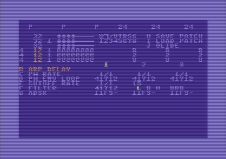
The numbers 1, 2 and 3 in the middle of the screen
stand for the three voices.

The number highlighted in white indicates the voice currently
selected, which can be changed by pressing the
keys 1, 2 and 3. Some
parameters can be edited only for one voice
at a time, so you
must first
select the voice you want to edit. These parameters are PW ENV LOOP (option
D), ADSR (option G) and the
oscillator tuning, located
at top right:

Using the cursor
down/up key you can increase or decrease
the pitch by
12 semitones (one octave) and
with the right/left key
adjust it
1
semitone more or less.
This
main
screen contains the only menu you'll use to edit
all settings. At this point, you can perform an initial sound test: by
pressing the space bar,
you'll enter the play mode. You'll see some characters rapidly changing
on screen, and if you press keys on your MIDI keyboard, you should be able
to hear the notes. The default mode is polyphonic,
allowing you
to play up to three notes
simultaneously. By pressing the
Return key you'll
return to the
edit mode; any character should stop changing on the screen.
By pressing the
keys A to M you can access the following options.
Only B to J are
visible
in the menu.
| A |
Wave tables and arpeggios editor
(see option K)
|
This is the most complex section, containing several parameters
explained below. The three upper rows
|
54276 ($D404)
Voice 1
|

|
|
54283 ($D40B) Voice 2
|
|
54290 ($D412) Voice
3
|
are the
waveforms editor, which basically
represents
a
sequence of
four states in the
registers 54276, 54283 and 54290. These SID registers determine
the oscillators' waveforms, as well as the synchronization, the
ring modulation effects, and the gate state. Each character
represents a state of the register at a given time unit. All 8 bits can be
switched on or off independently.

The numbers 1 to 8
correspond to the keys you need to press, but when I refer to bits, they are
numbered from 0 to 7 and from right to left.
|
Function
|
Noise
|
Square
|
Saw tooth
|
Triangle
|
Test
|
Ring
modulation
|
Synch.
|
Gate
|
|
Key
|
1
|
2
|
3
|
4
|
5
|
6
|
7
|
8
|
|
Bit
|
7
|
6
|
5
|
4
|
3
|
2
|
1
|
0
|
The first
four
states
are
swept in a loop from left to right during the ADS phase (when you
press a key
on the MIDI keyboard) and the last 4 states
are swept
in
the same way
during the R phase (when you release the key and the sound
starts to fade out). By combining different waveforms within the
same phase, distorted and metallic sounds can be generated.
The
three lower rows
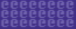
are the arpeggios editor.
|
| B |
Arpeggio speed |
Sets the speed at which arpeggios are swept. Arpeggios can be set as fixed
in the arpeggio editor or as pseudochords in
real time,
while playing several notes simultaneously (keyboard
mode 3 and mode 4). Valid
values range from 1 to 128.
|
| C |
Pulse width sweep speed,
square LFO on/off |
This synthesizer uses two
software-generated LFO to modulate the cutoff frequency and the
pulse width of the
square waveform, respectively. Although the SID can use
the third oscillator's output to hardware-generate an LFO, I left
out this built-in LFO, as it
sacrifies
the sound of voice 3.
Polytimb
64
actually features three independent
software
LFOs to modulate the pulse width
(PW)
of
each
of the three voices, but for the time being I'm using the same LFO
for
the square waveform of all
voices.
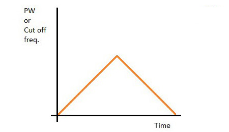
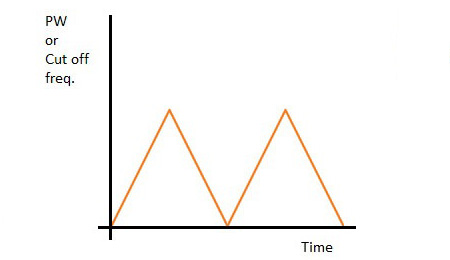
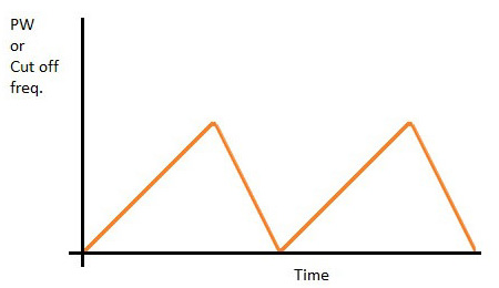
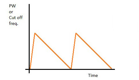
Here you
need to enter three values.
The first
one determines the speed of the ascending sweep through a defined PW
range (see option D). The second value does the same for the
descending sweep.
And the
third one sets whether the the LFO wave will be square (1) or a
varietion of triangle or sawtooth (0).
|
Enter "1,1,0" |
Enter "2,2,0" |
 |
 |
Enter "1,2,0" |
Enter "8,1,0" |
 |
 |
Enter "1,1,1" |
Enter "8,1,1" |
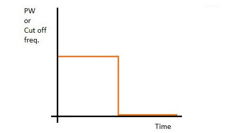 |
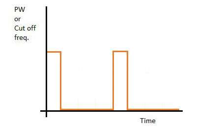 |
When the
LFO wave is square, the slash (/) between the values is displayed
in reverse video. For instance, here are the PW RATE values:
|
| D |
Pulse width envelope/loop |
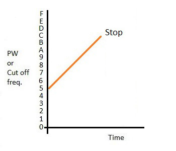
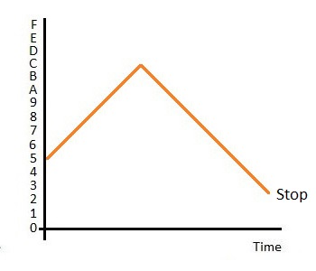
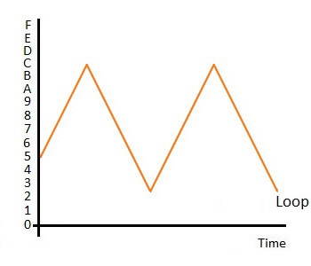
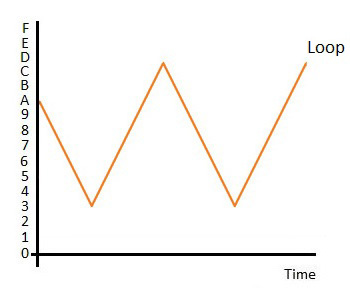
This controls the LFO as
well as a kind of primitive envelope for the pulse width (PW) by determining the
starting, highest, and lowest PW levels (first, second and third
digits, respectively). The fourth digit sets the initial direction
of the PW sweep (1 = ascending, 0 = descending) and the fifth digit
determines whether the PW stops sweeping once it reaches the lowest/highest
point for the first time (0), if it stops after reaching a second
lowest/highest point (1), or if it
continues sweeping up and down
indefinitely between the lowest and highest levels.
The range of
the
first three digits is between 0 and F. For the sake of
simplicity,
only the most significant byte of the PW can be selected
by the user. However, the PW sweeps
across the least significant
byte
(at the speed defined in option C).
In this
settings, the values are entered
using the
keys 0 to 9 and
A to F, shifting the
selected digit left and right with the
cursor keys.
Pressing the
Return key confirms the
selected values, and pressing T
copies the selected values to the PW envelopes of all voices.
|
| E |
Filter cutoff sweep speed, square LFO on/off, filter resonance |
This is the same as option C, but
in this case it applies to the filter cutoff frequency. In
addition to the three values explained in (C) you
must enter here
a fourth value between 0 and 15 for the filter resonance. For
instance, "1,1,0,15"
represents sweep speed up = 1, sweep speed
down = 1, no square LFO, and 15 (maximum) resonance. |
| F |
Filter cutoff envelope/loop |
Same as option D, but
it applies to modulating the filter cutoff frequency. Since
the SID cutoff frequency is 11 bits long, the maximum value you can
enter for the first three digits is 7 instead of F. |
| G |
Volume ADSR |
This is the amplitude
envelope generator. Unlike options D and E, this is a hardware
feature of the SID: registers 54277 (attack/sustain) and 54278
(sustain/release) for oscillator 1, registers 54285 and 54286 for
oscillator 2, and registers 54291 and 54292 for oscillator 3. The
values are entered by pressing the
keys 0 to F;
while
the left and
right cursor keys shift the selected digit, the
Return key confirms the entered values and the
T key copies them to all three voices.
There is a known bug in the SID chip
that
prevents the attack to start properly
for certain ADSR values,
resulting in no sound when you press a note key. More about this
here. |
| H |
Save patch |
Enter a name (max. 16 characters) for the patch you want to save.
|
| I |
Load patch |
Enter a name (max. 16 characters) for the patch you want to load.
|
| J |
Glide speed /
Vibrato |
Here six values must be entered: the first group of three values
is for glide (voice 1, 2 and 3) and the second group for the
vibrato (voice 1, 2 and 3).
The glide values determine
how
quickly (1 =
fastest, 255 slowest) a note's pitch increases or decreases when you
press a key on the
instrument. Three values separated by comma must be
entered, one for each voice. Very slow glide speeds
will produce audible "steps"
along the pitch variation, but for most "normal" speeds you'll hear
a continuous, smooth glide.
The range of values for
the vibrato is between 1 and 32. I haven't tried any values outside
this range, but I assume values beyond the range will cause strange
sounds or a lockup.
To
activate the glide
effect, it has to be set to one of the four ON
modes. With the keys F1
(voice 1), F3 (voice 2) and F5
(voice 3) you can sequentially select:
| @ |
Glide off |
| A |
Glide downwards: starting
from an octave lower than the
currently played
note and gliding up to the actual note. |
| B |
Glide upwards: starting
from an octave higher than the
currently played
note
and gliding down to the actual note. |
| C |
Glide from the
previously played
note in
one of the two sections of the keyboard (or just the entire
keyboard if it's not split) to the currently played note.
|
| D |
Glide from the
previously
to the currently played
note in
the other section of the keyboard (provided the keyboard is
split).
|
Basicaly, C and D
modes allow for independent portamento effects in each part of the keyboard,
when the keyboard is split. If the keyboard is split and you
select the same mode (either C or D) for voices played in
different parts, notes on different sections of
the keyboard may be linked by portamento, resulting in unwanted
or interesting effects.

In the current version,
the speed/rate of vibrato is
locked to the speed/rate of the glide (8 in the example
above), while the amplitude/amount del
vibrato (16) can be set on its own. This will be fixed in
future versions, to allow complete independence between both
types of modulation. For the time being, interesting effects
can still be produced. For instance, set the glide mode to
B for the three voices with the keys
F1, F3 and F5,
then press J
and enter the values 8,8,8,16,16,16. If you
use a triangle waveform in all voices, these values will
produce a ghostly sound.
|
| K |
Wave tables speed
|
Enter a delay value for each voice, separated by commas, to determine how
fast the sequence of waveforms is read in a loop (the higher the value, the
slower the sequence). More about this here.
Please remember this option, as its "K" is not listed in
the menu.
|
| L |
Enter POKEs manually |
This is a kind of debug option. In future updates I will list here
several memory addresses and values you can enter to adjust the
program's behaviour. The format is: memory address,value. |
|
M |
Fine tuning |
Enter the voice number (1, 2 or 3) followed by a comma and a value from 0
to 255, where 0 means no detuning at all. Detuning is more noticeable
when using two or three oscillators in unison (modes 2, 4 and 6), which
produces a "fat"
sound. For instance, select the keyboard mode 6 (3 voices played as monophonic), press M and then enter
"2,7" (detuning voice 2 by 7 units), then press M
again and enter "3,14" (detuning voice 3 by 14 units). Play some notes
to hear the difference: voice 1 is in tune, while voices 2 and 3 are
slightly detuned.
You can also enter 4 as the first value, which
assigns the same fine-tuning value to all voices. This is useful when you
want to set all voices perfectly tuned again: press M
and then enter "4,0".
|
|
N |
Glide distance in
glide modes A and B
(see J key
above) |
Sets how many semitiones above or below the pressed key the glide will
start from. The default value is 12. Three values, one for each
voice, must be entered separated by commas, for instance:
"24,24,24".
Please remember this option, as its "N" is not listed in
the menu.
|
The only value that can't be set from the
program is the SID volume. It is set by default to 15 (maximum), but it can be
changed manually in the line 33 of the BASIC code before running the program:
33 POKE54296,15+16*LP+32*BP+64*HP
Once you press the A key in the main menu, you
will
enter
this area of the screen, with the cursor
located in the middle of the top row.

Here you can edit a number of paramaters
using the
following keys:
-
General
-
Cursor keys:
move one space up, down, left or right within the central area. If you
move out on a side, you'll enter from the oposite
side.
-
Commodore Key + C: Copy the value of the current position.
-
Commodore Key + P: Paste a value into the current position.
-
Shift + 1 to 6: Copy the row you are
currently on to another row (1
- 6)
-
While being at one of
the 3 upper rows (waveforms)
-
Keys
1 to 8: switches on/off one bit of the 54276/54283/54290
registers for the time position you are at in the row's sequence.
-
Commodore Key
+ Keys 1 to 8: switch
on/off one bit of the 54276/54283/54290 registers at all time
positions in the row's sequence.
-
Keys F1, F2, F3 and
F4: selects at which
position (1, 2, 3 or 4 in red below) the
row's sequence loop is
restarted; the same value is used for all voices. For instance,
you can have a triangle waveform at the first position and square
waveforms at positions 2, 3, 4. Then you select 2 (F2) for the loop
restart. When you press a key in the MIDI keyboard, you'll hear a brief
triangle waveform and then a continuos square waveform. The waveform
sequence is read as: 1, 2, 3, 4 -> 2, 3, 4 -> 2, 3, 4 -> etc. With the
K key
in the main menu you can set how fast this sequence is read (in the
screenshot it has a delay of 32 for all voices).

-
While being at one of
the 3 lower rows (arpeggios)
-
Each time position contains a note played in an arpeggio when you play a
note in your keyboard. The arpeggios' notes are relative to the
fundamental note you play in the keyboard. The relative notes are
counted in semitones, from @
= 0 to L = 12 semitones above
the fundamental note. This means that four
@
will produce the note you play and with
L = 12 you'll hear that same
note one octave higher.
-
@
= 0, A = 1,
B = 2, C = 3,
D = 4,
E = 5, F = 6,
G = 7,
H = 8, I = 9,
J = 10,
K = 11, L = 12
semitones.
-
Examples: 1) The sequence
@DGJ
plays a mayor 7th arpeggio. 2) The sequence
@L@L
alternates between the fundamental note and its octave.
-
You can use arpeggios during the ADS phase and
revert
to
the plain
fundamental note when you release the key. In the example below, voice 1
plays a mayor 7th arpeggio while the note is hold down (green),
and the plain note when released (brown);
voice 2 plays the plain note while held down
(green)
and
alternates between the
fundamental note and its octave when released
(brown).
-
Keys F1, F2, F3 and F4:
selects
the position (1, 2, 3 or 4 in red
below)
where the row's
sequence loop restarts; different values can be set for each
voice. For
example, if you enter 2, the arpeggio will be played as:
1, 2, 3, 4 -> 2, 3, 4 -> 2, 3, 4, etc.
You can use the
B key in the main
to adjust how
fast this sequence is read (in the screenshot below, the delay
is set to 16
for all voices).
-
Keys 1 To 4: Set
the number of
notes
in
the arpeggio (yellow),
always starting from the first note. For
example, if you select 3, the
fourth position in the row will be ignored.

Filter settings
With the
following keys,
you can
toggle which voices routed through the filter
and
select the
type of filter to use:
-
Keys F2, F4 and F6:
set whether voice 1, 2
or 3
is filtered
and
reset the filter envelope
(B),
filtered without resetting the envelope
(A)
or
bypass the filter (@).
Repeatedly hitting these keys cycles through the options.
-
Shift + L: turns on/off the low-pass
filter.
-
Shift + H: turns on/off the high-pass
filter.
-
Shift + B: turns on/off the band-pass
filter.
In the
example below, the low-pass filtered is selected, voice 1 is bypassed (@), voice
is routed through the filter and resets the filter envelope (B) and voice voice 3
is filtered without resetting the envelope (A).

The most frequent problem I encountered was notes that
continued to sound when I released the key on the piano. The most common cause
behind this issue were low batteries in the MIDI controller. It's advisible to
use a power supply or ensure that batteries are fully charged.
Also, check that all wires and parts are properly soldered or
inserted in the breadboard.
To identify some problems you can check the board
as explained earlier. Every time you press a
key, the built-in LED on the Arduino should briefly blink, and the same should happen
when you release the key. If this is not the case, something went wrong with the
sketch upload or some components aren't properly connected in the circuit. If the LED
blinks but the C64 doesn't produce any sound, then the problem lies somewhere
between Arduino and the C64.
Another issue I experienced frequently: in the MIDI OUT
port of my Keyboard I have a MIDI "Y" cable connected, which I use to send the MIDI signal
to two different devices. Even if the second device is off, it seems as some
MIDI bytes were lost on their way to the C64, causing some notes to remain ON
even after I released the note on my keyboard.
Contact: Ariel del Rio -> arieldr74@gmail.com


